How Electromechanical Dental Chairs Operate

Understanding the Core Components of an Electromechanical Dental Chair
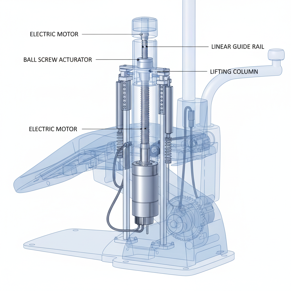
To appreciate how an electromechanical chair operates, it’s essential to first understand its primary components. Unlike hydraulic systems that rely on fluid pressure, electromechanical chairs use a combination of precisely controlled motors and mechanical linkages to achieve movement. This design choice directly impacts the chair’s performance, reliability, and maintenance profile.
The Drive System: Electric Motors and Actuators
The heart of the system is a high-torque DC electric motor. This motor is the prime mover, providing the rotational force needed to lift and tilt the chair. When selecting these motors, a critical engineering principle is to incorporate a safety margin of 30–50% on the torque rating. This ensures the motor can handle unexpected resistance—such as a brief stall or a patient shifting their weight—without overheating or failing. This over-specification is a hallmark of durable, long-lasting chair design.
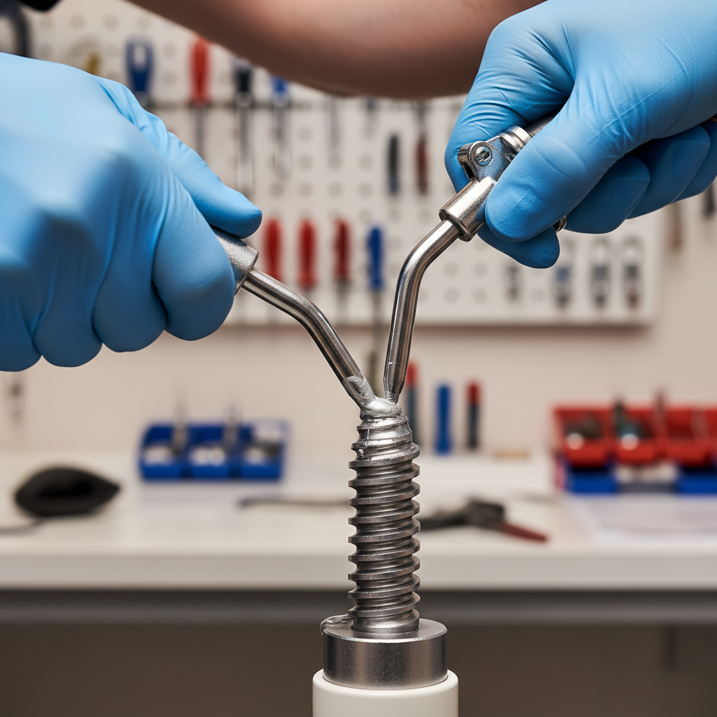
The Transmission: Lead Screws and Ball Screws
The motor’s rotational output is translated into the smooth, linear (up and down) motion of the chair via a screw-based transmission. Two common types are used:
- Lead Screws: These are a cost-effective and reliable option, featuring helical threads that engage with a matching nut. They are self-locking, meaning they can hold the chair’s position without power, but they have higher friction and are less efficient.
- Ball Screws: These are more advanced, using a series of ball bearings that roll between the screw and nut. This design significantly reduces friction, improving efficiency and providing a smoother feel. While more expensive, they are often used in high-end chairs for their performance and longevity.
Regardless of the type, this screw mechanism is a common wear point, especially if lubrication schedules are not followed, leading to increased friction and motor strain.
The Guidance System: Linear Guides
To ensure the chair moves vertically without tilting or binding, it runs along one or more linear guides or rails. These components are critical for stability, providing a rigid and precise path for the lifting mechanism. A robust guidance system prevents side-to-side play, ensuring the patient feels secure and the chair operates smoothly throughout its range of motion.
The Control System: PCBs, Encoders, and Limit Switches
The “brain” of the chair is its main printed circuit board (PCB). It receives commands from the operator’s controls (foot pedal or buttons) and precisely manages the motor. To achieve this, it relies on key feedback and safety components:
- Encoders: These devices track the motor’s rotation, providing real-time feedback to the control board about the chair’s exact position. This allows for programmable memory positions and controlled acceleration/deceleration.
- Limit Switches: These are physical switches placed at the top and bottom of the chair’s travel path. They signal the controller to cut power to the motor when the chair reaches its maximum or minimum height, preventing mechanical damage. Over time, repeated micro-impacts can cause these switches to drift, requiring recalibration.
From Button Press to Patient Repositioning: The Operational Flow
The sequence of events in an electromechanical chair is a clear example of a closed-loop control system. This ensures that every movement is precise, repeatable, and safe.
- User Command: The dental professional presses a button on the footswitch or chair-side controls to raise, lower, or recline the chair.
- Signal to PCB: The control board receives this input and determines the direction and required speed of the motor.
- Motor Actuation: The PCB sends a controlled electrical current to the motor, which begins to turn the lead screw or ball screw.
- Linear Motion: As the screw rotates, the nut attached to the chair’s lift arm travels along the screw’s threads, smoothly moving the chair up or down.
- Positional Feedback: Throughout the movement, the encoder constantly reports the motor’s rotation back to the PCB. The PCB uses this data to adjust motor speed for smooth starts and stops and to halt the chair at pre-set memory positions.
- End of Travel: If a command continues until the chair reaches its physical limit, the limit switch is triggered, signaling the PCB to immediately stop the motor.
Engineers typically target a vertical travel speed of 2–8 mm/s. This range provides an ideal balance, offering cycle times that are efficient for the operator while ensuring the movement is slow and smooth enough to be comfortable for the patient.
The Critical Role of Safety Mechanisms
Safety is paramount in any medical device. Electromechanical chairs incorporate several layers of protection. Beyond the limit switches, the Emergency Stop (E-stop) function is crucial. In a well-designed system, hitting the E-stop does more than just interrupt power to the motor. The most robust designs incorporate a mechanical brake or lock on the transmission. This prevents any possibility of the chair drifting downward in a power-loss scenario, a key safety feature that aligns with the quality management principles outlined in standards like ISO 13485:2016.
Electromechanical vs. Hydraulic Lifts: A Technical Comparison
When choosing a dental chair, one of the most fundamental decisions revolves around the lift system. Both electromechanical and hydraulic technologies have their place, but they offer different trade-offs in performance, maintenance, and long-term value. Understanding these differences is crucial for clinic owners and technicians.
| Feature | Electromechanical System | Hydraulic System |
|---|---|---|
| Precision & Repeatability | High. Encoder feedback allows for exact, repeatable memory positions. | Moderate. Prone to slight thermal drift and minor position changes over time. |
| Smoothness of Motion | Excellent. Modern DC motors and controllers provide very smooth starts and stops. | Excellent. Traditionally known for exceptionally smooth motion, though this advantage has narrowed. |
| Operating Noise | Low. The sound is typically a quiet, low-frequency hum from the motor. | Moderate. Can produce more noise from the hydraulic pump, which is often housed separately. |
| Maintenance & Reliability | Predictable. Maintenance involves periodic lubrication of screws and guides. Wear parts (motor brushes, screws) have long, predictable lifespans. No risk of leaks. | Complex. Requires checking for fluid leaks and periodic fluid changes. A leak can be catastrophic, causing downtime and potential floor damage. |
| Installation & Footprint | Simple. Self-contained unit. No external pumps or hydraulic lines are needed. | More Complex. Requires a separate hydraulic pump unit and routing of hydraulic lines, increasing installation complexity. |
| Environmental Concerns | Minimal. No oils or fluids to dispose of. Lower energy consumption. | Higher. Hydraulic fluid requires proper disposal. Leaks can create an environmental and safety hazard in the clinic. |
Debunking a Common Myth: “Hydraulic Chairs Are Always Smoother”
A persistent myth is that hydraulic systems are inherently superior in smoothness. While this was largely true of older, simpler electromechanical designs, modern technology has closed the gap. High-quality electromechanical chairs that use PWM (Pulse Width Modulation) controllers and precision ball screws offer motion that is virtually indistinguishable from their hydraulic counterparts. Any perceived “jerkiness” in a modern electromechanical chair is typically a sign of a low-cost, under-engineered drive system, not a fundamental flaw in the technology itself.
A Practitioner’s Guide to Maintenance and Troubleshooting
One of the primary advantages of electromechanical chairs is their straightforward maintenance. With proactive care, these systems can deliver decades of reliable service. These practices are essential for ensuring compliance with quality systems like those mandated by the FDA under 21 CFR Part 820.
Preventive Maintenance Checklist
- Scheduled Lubrication (Critical): The lead screw or ball screw and linear guides are the most critical maintenance points. In a clinic with normal usage, they should be re-lubricated every 6–12 months. For high-volume settings, this interval should be shortened to every 3–6 months. Insufficient lubrication is the leading cause of premature wear.
- Fastener Inspection: After the first ~1,000 operational cycles (typically within the first few months of use), it is best practice to check and tighten all critical fasteners on the frame and motor mounts. Afterwards, an annual check is sufficient.
- Cable & Harness Check: Regularly inspect all electrical cables, paying close attention to areas where they flex during chair movement, such as near hinge pivots. Look for signs of abrasion or kinking.
- Functional Tests: Periodically run the chair through its full range of motion to ensure smooth travel and verify that all limit switches are functioning correctly.
A Technician’s Troubleshooting Workflow
When a chair malfunctions, a systematic approach can quickly identify the root cause. This field-proven workflow isolates the problem efficiently:
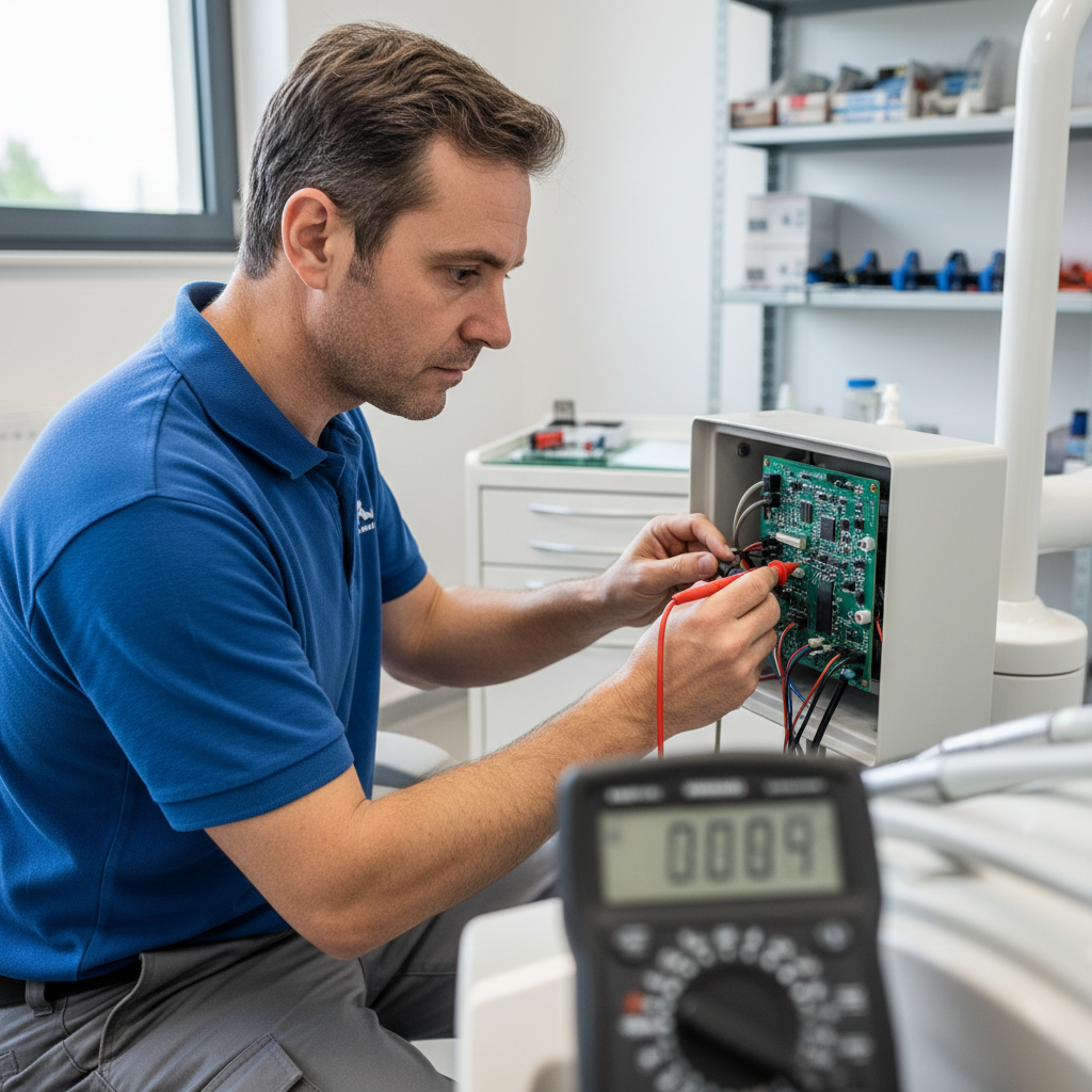
- Verify Power: Always start with the basics. Confirm that the chair is receiving mains power and has a solid protective earth connection.
- Measure Motor Current: Use a clamp-on ammeter to measure the motor’s idle current. Establishing a baseline when the chair is new can make it easy to spot downstream issues like increased friction or a failing motor later on.
- Log Encoder Feedback: Run a full, low-speed stroke of the chair while logging the encoder output. The data should show a smooth, consistent count. Jumps or dropouts in the data point to a faulty encoder, a loose connection, or a failing control board.
- Inspect Mechanical Linkages: If electrical checks pass, perform a close physical inspection of the screw, nut, and guide rails. Look for signs of excessive wear, debris, or lack of lubrication.
- Check Limit Switches: Finally, manually actuate the limit switches to ensure they send a stop signal to the controller. Check their physical mounts for any signs of drift or damage.
If you observe positional drift exceeding 1-2 mm over a full stroke, the most common culprits are a loose encoder connector or “soft” mechanicals, such as a flexing frame or loose motor mountings. These issues should be addressed immediately to maintain the chair’s precision, a key requirement for devices sold in regulated markets like the European Union under the EU MDR.
Key Takeaways
Electromechanical dental chairs represent a mature, reliable, and precise technology for patient positioning. Their design, centered on a simple motor-and-screw mechanism, offers significant advantages in precision, low maintenance, and operational cleanliness compared to hydraulic alternatives.
By understanding the core components and adhering to a simple preventive maintenance schedule, clinic owners and technicians can ensure their chairs operate safely and efficiently for years. This focus on durability not only improves clinic uptime but also has a direct positive impact on its financial health, as explored in How Chair Durability Impacts Your Clinic’s Financial Health. Ultimately, the move toward electromechanical systems reflects a broader industry trend toward cleaner, more precise, and more easily serviceable equipment.
Disclaimer: This article is for informational purposes only and does not constitute professional medical or engineering advice. Always consult the manufacturer’s service manual and follow certified procedures when maintaining or repairing medical equipment. If you have any doubts, contact a qualified service technician.
References
About the Author